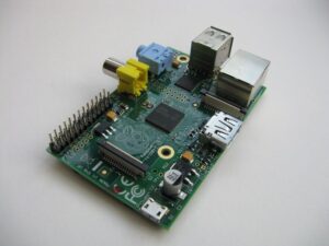
Back in February 2013 I wrote an article entitled “Hacking a Fireplace”. In that article I wrote about how I used an Arduino to create an interface that would allow me to directly control my fireplaces from my home automation system. That solution worked great and I was successful in running two fireplaces from the single controller for a year with no issues. What I didn’t like though was that the completed project was bulky and I wanted something much smaller that I could put under the fireplace, thus out of sight! To accomplish this, I decided to buy a couple of Model B Raspberry Pi’s to replace the Arduino.

Following is how I set them up.
WARNING: Let me interject here that one should exercise EXTREME caution before deciding to implement any kind of automated home controls such as those I will outline below! If you’re not comfortable dealing with electrical circuits then STOP here. Also be aware that your fireplace is supplied with natural gas or propane and working with its components presents a hazard. If you don’t know what you’re doing STOP and hire a professional to help you.
Prep Work
The first thing I did was set my DHCP server up to assign specific addresses to each Pi. These are the addresses that my HA system uses to trigger the on/off events.
Server Setup
Start by installing Raspbian. My implementations will be headless so I chose not to run a desktop thus reducing a little bit of overhead. There are tons of install examples online so I won’t cover that here. Once complete, run:
sudo raspi-config
Now choose to expand the filesystem and reboot.
Install Software
sudo su
apt-get install php5-cli php5-curl apache2 php5 libapache2-mod-php5 vim
Install WiringPi
I’m a CLI guy and WiringPi lets me control the GPIO pins via a command line utility – LOVE that!!
git clone git://git.drogon.net/wiringPi
cd wiringPi
git pull origin
./build
Setup Wi-Fi
There is no GUI to configure Wi-Fi so we’ll need to configure it manually. Don’t forget to use your own SSID and password.
sudo su
vim /etc/network/interfaces
Replace the contents with the following:
auto lo

iface lo inet loopback
iface eth0 inet dhcp

#iface wlan0 inet manual

auto wlan0
allow-hotplug wlan0
iface wlan0 inet dhcp
wpa-ssid "yourSSID"
wpa-psk "yourPASSWORD"

iface default inet dhcp
wpa-roam /etc/wpa_supplicant/wpa_supplicant.conf
By default, Raspian will try to manage the adapter’s power use by putting it to sleep. This causes all kinds of issues so we need to disable that “feature”.
sudo su
vim /etc/modprobe.d/8192cu.conf
Now paste the following and reboot:
# Disable power saving
options 8192cu rtw_power_mgnt=0 rtw_enusbss=1 rtw_ips_mode=1
Interfacing the Relay to the Raspberry Pi
I picked up a couple of these simple single-relay boards off of Amazon:

Then I wired the relay to the Raspberry Pi as follows:
| Relay | Raspberry Pi |
|---|---|
| vcc | 3v3 |
| gnd | gnd |
| in | #4 |
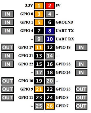
Here’s a layout of the Raspberry Pi pin layout along with the WiringPi assigned pin numbers:

My relay is a single pole, double throw relay. Connect to the common and normally open side of the relay and use the following commands (note that wiringPi changes the pin numbers):
gpio mode 7 out to setup the gpio pin for output mode
gpio write 7 1 to turn off (high)
gpio write 7 0 to turn on (low)
If connecting to the normally closed side of the relay the commands would be opposite of the above to turn off/on.
With my setup, when connecting this way, it is CRUCIAL to use the normally open side of the relay. If connecting to normally closed, a power failure would turn the fireplace on – NOT the desired result.
Startup Script
In order for this solution to function correctly we need to initialize the Raspberry so that our GPIO pin behaves in the desired way.
sudo su
vim /etc/init.d/relayinit
Now past the following:
#! /bin/bash
# /etc/init.d/relayinit

# Carry out specific functions when asked to by the system
case "$1" in
start)
echo "Starting Relay"
# Turn 7 on which keeps relay off
/usr/local/bin/gpio write 7 1
#Start Gpio
/usr/local/bin/gpio mode 7 out
;;
stop)
echo "Stopping gpio"
;;
*)
echo "Usage: /etc/init.d/relayinit {start|stop}"
exit 1
;;
esac

exit 0
Make the file executable:
chmod 777 /etc/init.d/relayinit
Now tell your pi to run this script at boot:
update-rc.d -f relayinit start 4
(Note: You can safely ignore the “missing LSB tags” warning.)
Fireplace Code
Now we need to set up an interface on the Raspberry Pi so we can control the relay from an external source (e.g. my HA system). A simple PHP application will serve this purpose perfectly:
vim /var/www/fireplace.php
Now paste the following:
<?php

#Turn Fireplace Off
if ($_GET["RELAY2"] == "2") {
exec('gpio write 7 1',$output, $return);
if ($return == 0) {
echo "2";
} else {
echo "problem";
}
} elseif ($_GET["RELAY2"] == "1") {
#Turn Fireplace On
exec('gpio write 7 0',$output, $return);
if ($return == 0) {
echo "1";
} else {
echo "problem";
}
} else {
#Get status
exec('gpio read 7',$output, $return);
if ($output[0] == 0) {
echo "on";
} elseif ($output[0] == 1) {
echo "off";
} else {
echo "unknown";
}
}
?>
Now all I need to do is wire the relay in parallel with the Skytech system and make some minor tweaks to my HA scripts and I’m off an running.
Until next time – GEEK OUT!
~GT~


I saw you interfaced the remote control. The remote control receiver plugs into the valve. Do you know our could you interface the valve control directly like the remote does?
Mike – That’s exactly what I did with this new version. I connected the relay to the same terminals that the SkyTech Receiver connects to. If the power fails and the Pi is down then we can still light the fireplace with the SkyTech remote. Works like a charm.
Pingback: Geek-Tips » Hacking a Fireplace
This is exactly what I am looking for. I also need to control flame up/down via home automation. Is that possible? I am not comfortable programming this myself. Do you have a professional that you recommend? I need to do this to about 20 fireplaces.
Do you have any pictures/information about how you wired the relay into the Skytech system using this approach? Would very much like to recreate this using a relay and the ESP8266. Thanks! Great project